Industrial thermal insulation is more than a layer wrapped around hot pipes. It affects energy use, worker safety, equipment performance, and maintenance costs. In China’s diverse industrial market, insulation materials must suit factories, chemical plants, power stations, cold rooms, and process lines. Mineral wool, calcium silicate, aerogel blankets, and cellular glass each offer different advantages. The best choice depends on operating temperature, moisture exposure, mechanical stress, fire requirements, and installation quality.
Small details matter.
A damaged valve cover can release significant heat. Wet insulation can lose much of its effectiveness. Poorly sealed joints may create cold bridges, condensation, or corrosion beneath insulation. This article examines how to improve thermal insulation in industrial facilities through material selection, accurate thickness design, protective jacketing, and regular inspection. Experienced engineers normally compare thermal conductivity, service temperature, water resistance, durability, and lifecycle cost before approving a system. Recognized testing methods and local safety requirements should guide every decision. Supplier documentation also needs careful verification, because marketing claims are not always equal to field performance. Even premium insulation can fail when workers cut it inaccurately or leave gaps around supports. That reality deserves attention.
A practical improvement plan should begin with a site survey. Infrared inspections, surface-temperature measurements, and maintenance records can reveal hidden losses. Engineers can then prioritize high-temperature lines, tanks, flanges, and frequently accessed equipment. Performance should be reviewed after installation, not assumed. Conditions change. Humidity rises, cladding loosens, and production temperatures fluctuate. Reliable insulation therefore requires sound design, skilled installation, documented inspection, and willingness to correct earlier decisions.
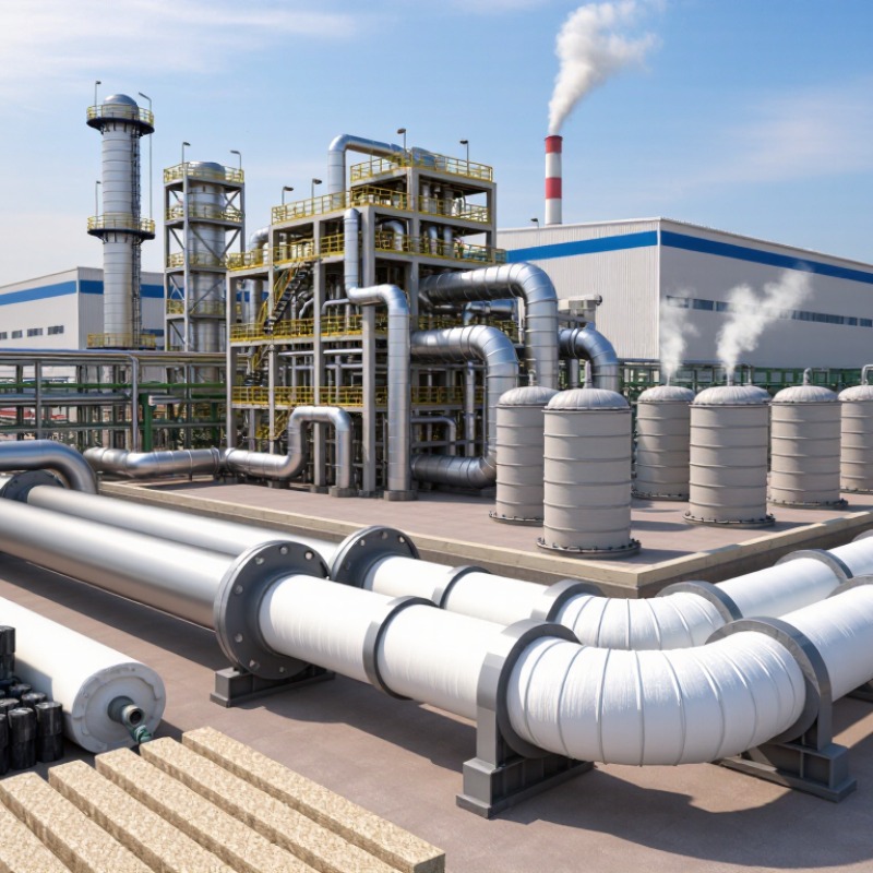
Effective thermal insulation in industry starts with the operating conditions, not a catalog description. Engineers should check temperature, humidity, pressure, vibration, and exposure to chemicals. A material with low thermal conductivity can still perform poorly when moisture enters its joints. Insulation is not magic.
During plant inspections, the weakest points are often valves, flanges, supports, and damaged jacketing. A warm pipe may look properly covered, yet a small gap can create heat loss and surface condensation. Installers should seal seams carefully and protect the system from rain, oil, and impact. For cold equipment, a continuous vapor barrier is essential. One break can spread moisture beneath the insulation.
Material selection should follow measured data, recognized testing methods, and applicable safety requirements. Standards such as ISO 12241 can guide thermal calculations, while laboratory results should reflect real operating temperatures. Thickness must balance energy performance, available space, maintenance access, and fire behavior. The cheapest option is rarely the most reliable over time. It may also create higher replacement costs.
A good design includes inspection points and a maintenance schedule. Technicians can use surface temperature checks and moisture detection to find hidden failures. Results should be recorded, not guessed. Still, calculations have limits. Field conditions change, and installers sometimes work around incomplete drawings. That weakness deserves attention before construction begins.
Lower thermal conductivity indicates better insulation performance because less heat flows through the material. The values shown are representative dry-state conductivity values at approximately 24°C; actual performance varies with temperature, density, moisture, and installation quality.
Choosing industrial insulation in China requires more than comparing thermal conductivity. I have seen a low-value material fail beside a hot pipe after moisture entered its joints. Compare conductivity at the actual operating temperature, not only the catalog value. A material rated at 0.035 W/m·K in a laboratory may perform worse at 300°C. Check density, compressive strength, water absorption, fire behavior, and service temperature. These figures show how insulation may survive handling, vibration, and cleaning.
Tips: Build a simple comparison table. Record conductivity, thickness, temperature range, moisture resistance, installation method, and maintenance needs. Test samples under realistic conditions when possible. For example, place a jointed section near a controlled heat source and measure its surface temperature. Keep records. Small gaps can increase heat loss and create burn risks. This detail is often overlooked.
For process equipment, insulation should also support worker safety and stable production. Fibrous products may fit complex shapes, while rigid boards offer stronger mechanical protection. Foamed materials may resist moisture, but their temperature limits require careful checking. Do not judge performance from one test. Installation quality changes the result significantly. A rushed site survey can produce the wrong thickness, and I have made that mistake in early project planning. Recheck heat-loss calculations, weather exposure, and repair access before approval. Field conditions vary.
Industrial insulation should be selected from operating conditions, not from price alone. A hot steam pipe may need insulation above 300°C, while a chilled-water line needs moisture protection. Measure surface temperature, humidity, pressure, vibration, and available space before choosing a material. Small errors matter.
For dry, high-temperature equipment, mineral-based insulation can reduce heat loss and protect workers from burns. In damp areas, a closed-cell structure and sealed outer jacket may prevent water intrusion. Chemical plants require compatibility checks because solvents, acids, or alkalis can damage insulation layers. Outdoor systems also need resistance to sunlight, rain, and mechanical impact.
Measure twice.
Installation quality often decides real performance. Gaps around valves, flanges, and supports can create cold bridges or dangerous hot spots. Use tested thermal data at the actual operating temperature, rather than relying on room-temperature ratings. Fire behavior, smoke generation, service life, and maintenance access should be verified with qualified engineers and relevant local standards. A thicker layer is not always better; it may trap moisture or obstruct inspection. This is where many projects need more honest review. Calculate energy savings, inspect the first installed section, and adjust the design before completing the entire system.
| Industrial Condition or Application | Recommended Insulation Material | Typical Service Temperature Range | Typical Thermal Conductivity at Approximately 20°C | Moisture and Water Behavior | Key Selection Advantages | Important Limitations | Practical Improvement Measures |
|---|---|---|---|---|---|---|---|
| Hot process pipes, boilers, furnaces, ducts and equipment with high fire exposure | Mineral wool or high-temperature rock wool | Approximately -40°C to 650°C; some specialized products are rated higher | Approximately 0.035–0.060 W/m·K | Non-combustible, but water absorption can reduce thermal performance if the insulation becomes wet | Non-combustible, widely available, relatively economical and suitable for complex industrial shapes | Requires a weatherproof vapor barrier or metal jacketing in wet or outdoor areas; performance decreases when compressed or saturated | Use the correct thickness, seal joints, avoid compression, install weatherproof jacketing and protect against thermal bridges |
| Very high-temperature piping, boilers, kilns and high-temperature equipment | Calcium silicate | Approximately 650°C to 1,000°C, depending on product formulation | Approximately 0.055–0.100 W/m·K | Can absorb water; drying may be required after wetting | Rigid, strong under compression and suitable for high-temperature industrial service | More brittle than flexible fiber products and may require careful handling and joint detailing | Use rigid supports, staggered joints, protective jacketing and expansion allowances around hot equipment |
| Cryogenic pipelines, liquefied-gas systems and low-temperature storage tanks | Cellular glass | Approximately -260°C to 430°C | Approximately 0.038–0.055 W/m·K | Closed-cell structure with very low water absorption and strong moisture resistance | Non-combustible, vapor-tight when properly jointed, dimensionally stable and resistant to water ingress | Rigid and relatively brittle; joints and penetrations must be carefully sealed | Install a continuous vapor-control system, seal every joint and penetration, and prevent mechanical damage during maintenance |
| Refrigerated process lines, chilled-water pipes and moderate-temperature equipment | Polyisocyanurate (PIR) foam | Approximately -180°C to 150°C, subject to the specific product and facing system | Approximately 0.022–0.030 W/m·K | Low water absorption when the facing and joints remain intact; vapor sealing is essential for cold service | Low thermal conductivity, lightweight and space-efficient for many industrial systems | Combustibility and smoke performance depend on the complete system; prolonged high temperatures can damage the foam | Use approved fire protection, continuous vapor sealing, protected supports and correctly sized pipe sections |
| Cold rooms, chilled equipment and process systems requiring high insulation efficiency in limited space | Phenolic foam | Approximately -50°C to 120°C | Approximately 0.020–0.028 W/m·K | Closed-cell structure provides useful moisture resistance, but joints and facings still require sealing | Very low thermal conductivity and good space-saving performance | Temperature range is lower than that of mineral wool, calcium silicate and cellular glass; can be brittle | Use a continuous vapor barrier, protect edges, minimize gaps and confirm fire classification for the complete assembly |
| Complex equipment, valves, flanges and retrofit projects where insulation thickness is restricted | Flexible aerogel blanket | Approximately -200°C to 650°C, depending on composition and facing | Approximately 0.015–0.025 W/m·K | Generally hydrophobic, but seams and penetrations still need weather and vapor protection | Very low thermal conductivity, thin profile, flexible installation and good retrofit capability | Higher material cost; dust control, correct overlap and mechanical protection may be required during installation | Use sufficient layers, stagger overlaps, secure the blanket without excessive compression and add a durable outer jacket |
| Hot tanks, ducts, industrial ovens and applications requiring non-combustible insulation with moderate mechanical loading | Perlite insulation | Approximately -40°C to 650°C, depending on product type | Approximately 0.045–0.070 W/m·K | Porous structure can absorb moisture; external weather protection is important | Non-combustible, mineral-based and suitable for a range of hot industrial applications | Can settle or lose performance if poorly installed; generally requires more thickness than high-performance foams or aerogel | Provide proper containment, prevent water ingress, use suitable supports and inspect for settlement during maintenance |
| Outdoor process equipment exposed to rain, humidity or wash-down conditions | Cellular glass or closed-cell foam with a sealed jacketing system | Selected according to the process temperature; commonly approximately -180°C to 430°C for cellular glass | Approximately 0.025–0.055 W/m·K, depending on the selected material | Cellular glass offers very low water absorption; closed-cell foams require intact facings and sealed joints | Reduces water-related loss of insulation performance and helps limit corrosion under insulation when correctly detailed | Incorrect jacketing, open seams or damaged vapor barriers can allow water ingress | Use sloped jacketing, sealed laps, drainage details, protected penetrations and regular inspection of the outer weather barrier |
| High mechanical-load areas, pipe supports, walkways and locations subject to impact | Calcium silicate or high-density cellular glass | Approximately -180°C to 1,000°C, depending on the selected material | Approximately 0.045–0.100 W/m·K | Moisture resistance varies; cellular glass generally performs better against water ingress | Rigid structure and better resistance to compression than many flexible insulation products | Rigid materials require accurate cutting, properly designed supports and impact protection | Use load-bearing inserts, avoid crushing at supports, provide protective covers and maintain alignment at joints |
| Fire-sensitive industrial areas, escape routes and equipment requiring low flame spread | Mineral wool, calcium silicate or cellular glass | Approximately -40°C to 1,000°C, depending on material and product design | Approximately 0.035–0.100 W/m·K | Water protection is still required for fibrous or porous materials | Mineral-based options are generally non-combustible; suitable for high fire-resistance design when tested as a complete system | Fire performance depends on facings, binders, jacketing, joints and support details—not insulation alone | Verify the complete assembly against applicable fire standards and protect all penetrations, seams and service openings |
| Energy-loss reduction on steam lines, hot-water lines and process equipment | Mineral wool, calcium silicate or aerogel blanket | Approximately 100°C to 650°C; select according to operating and upset temperatures | Approximately 0.015–0.100 W/m·K | Moisture control is necessary to preserve the calculated thermal resistance | Suitable material options are available for both standard and space-restricted systems | Insufficient thickness, wet insulation, open joints and uninsulated valves can significantly increase heat loss | Calculate thickness from operating temperature, ambient conditions, surface-temperature limits and energy targets; insulate valves and flanges where practical |
| Systems requiring condensation control on cold surfaces | Closed-cell foam, cellular glass or a fully sealed vapor-barrier system | Approximately -260°C to 150°C, depending on the selected material | Approximately 0.020–0.055 W/m·K | Requires a continuous vapor barrier with sealed joints, penetrations and support locations | Helps keep the outer surface above the dew point and limits condensation-related corrosion and dripping | Small gaps, damaged facings or thermal bridges can cause local condensation even when average thickness is adequate | Design for dew-point control, seal every discontinuity, use low-conductivity supports and inspect the vapor barrier after installation |
Installing industrial thermal insulation begins with a surface survey, not with opening cartons. Check pipe temperature, operating cycles, corrosion, moisture, and access around valves. Select material suited to the temperature range, mechanical demands, and surrounding environment. A clean, dry surface gives the insulation a dependable starting point. Remove loose rust and repair leaks before covering anything. For hot equipment, allow safe cooling or follow a controlled installation procedure. For cold lines, keep the substrate dry and prevent condensation. Gaps matter.
Fit sections tightly, while avoiding excessive compression that reduces their designed thickness. Stagger joints between layers and seal every visible seam with compatible materials. Use secure bands or mechanical fasteners, but do not crush the insulation. At elbows, flanges, and supports, shape the material carefully around movement points. Leave service access where maintenance teams need it. This detail is often missed. A vapor retarder belongs on the warm side of cold insulation systems. Seal penetrations around instruments, drains, and supports with particular care.
Protection starts after installation. Install a durable outer jacket where impact, water, chemicals, or weather may damage the insulation. Slope horizontal covers so rainwater cannot collect at joints. Keep the jacket tight, but provide movement allowances for thermal expansion. Inspect the system after its first operating cycle. Look for wet spots, loose bands, hot points, and damaged seals. I have seen excellent materials fail because one small penetration remained open. A final inspection should record temperatures, photographs, and repairs. The process is not perfect. Review weak areas honestly, then improve the next installation.
Industrial insulation loses efficiency when moisture, damaged jackets, or open joints appear. These small faults can raise surface temperatures and energy costs. During site inspections, I often find that insulation thickness is acceptable, but installation details are weak. Sealed seams, protected pipe supports, and dry surfaces matter greatly. A perfect installation is unrealistic. Regular correction is more practical.
Tips: Check insulation after maintenance work, especially around valves and flanges. Use thermal imaging to locate unusual hot spots. Repair wet sections quickly, because trapped moisture reduces thermal resistance. Keep outer cladding tight and inspect it after heavy rain or vibration. Record findings with photos and temperature readings.
Material selection should match operating temperature, humidity, fire requirements, and mechanical exposure. High-temperature lines need stable insulation that will not shrink easily. Cold systems require continuous vapor barriers to prevent condensation. Even the best material performs poorly when compressed or badly fitted. This is an area where teams sometimes focus too much on product specifications. Installation quality deserves equal attention. Schedule inspections during normal production, not only during shutdowns. Small losses become expensive when they continue unnoticed.
Check temperature, humidity, pressure, vibration, chemicals, and operating cycles. A low-conductivity material may fail when moisture enters its joints.
Inspect valves, flanges, supports, seams, penetrations, and damaged outer coverings. Small gaps can create heat loss and surface condensation. Gaps matter.
Keep surfaces clean and dry. Remove loose rust and repair leaks first. For cold systems, prevent condensation before covering the surface.
Fit sections tightly without excessive compression. Stagger joints between layers. Seal visible seams with compatible materials. Avoid crushing the insulation with bands.
A continuous vapor barrier limits moisture movement beneath cold insulation. Seal penetrations around instruments, drains, supports, and other openings. One break can spread moisture.
Shape materials carefully around movement points and irregular fittings. Keep maintenance access available. This detail is often missed.
Use a durable outer jacket where water, chemicals, impact, or weather may cause damage. Slope horizontal covers so rainwater cannot collect at joints. Allow movement from thermal expansion.
Check surface temperatures, moisture, wet spots, loose fasteners, hot points, and damaged seals. Record readings, photographs, and repairs instead of relying on memory. Measure it.
Inspect it after the first operating cycle. Conditions may differ from the drawings. We sometimes miss one penetration or weak joint. Review those failures honestly.
Effective thermal insulation is essential for industrial facilities seeking to control operating temperatures, improve energy efficiency, and protect workers and equipment. This summary explains what makes insulation effective, including low thermal conductivity, suitable thickness, moisture resistance, durability, and compatibility with the operating environment. It also outlines how to compare materials based on heat resistance, fire performance, mechanical strength, service life, installation requirements, and total cost rather than price alone. Selecting the right solution requires considering temperature ranges, humidity, chemicals, vibration, outdoor exposure, and the shape of pipes, tanks, ducts, and processing equipment.
The article also describes practical methods for how to improve thermal insulation in industrial facilities. Proper surface preparation, accurate fitting, sealed joints, protective cladding, and effective moisture control are critical during installation. Regular inspections should identify damaged coverings, gaps, compression, corrosion, and water intrusion before energy losses increase. By combining suitable material selection, careful installation, protective measures, and scheduled maintenance, industrial operations can reduce heat transfer, lower energy consumption, improve process stability, and extend the service life of insulation systems.

Jonas Build